3D Inspection & Quality Control (quickly)
The 3D scanned data is compared to that of CAD model for knowing the difference in the following:
- Geometry variations in terms of dimensions
- Profile match/mismatch that are otherwise not possible to compare
- Acceptance of the part withint given range of tolerance for GO/NOGO certification
- Re-work areas of the part/tooling if there is significant mismatch
- Communication of the quality & process control to end-customers


CAD file is compared to that of actual casting by the formats of IGES, STEP or para-solid data

The actual casting is 3d scanned and brought in the form of STL data for comparison.

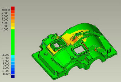
The comparison is carried out using inspection software to get numerical/graphical deviations.

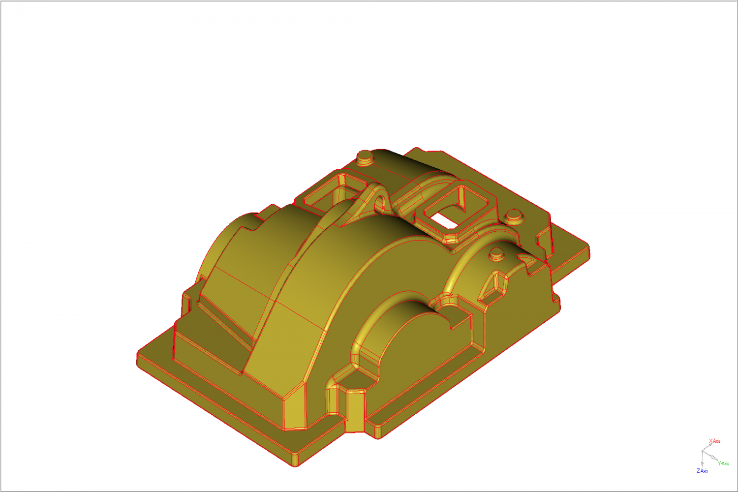
CAD Model

CAD Model is super-imposed to the Scan data using alignment tecniques

Resulting variations is displayed graphically with colorific values and also by numerical annotations
